


-
Address:
-
Phone: +65 8914 6529
-
Email: [email protected]

 English
Your cart
0 items
Shopping cart is empty (0 item)
English

In the manufacturing of low and medium-voltage electrical switchgears, the fabrication of copper and aluminum busbars requires strict dimensional accuracy and pristine surface finishes. Traditional hole-making methodologies, such as deploying high-speed twist drills or magnetic drill presses, introduce significant operational inefficiencies. Mechanical drilling generates high thermal friction, distorts the molecular structure of conductive metals, and leaves metallic burrs around the perimeter of the hole. In high-amperage electrical panels, these burrs act as concentration points for electrical stress, which subsequently leads to micro-arcing, thermal accumulation, and compromised joint conductivity.
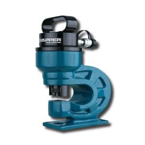
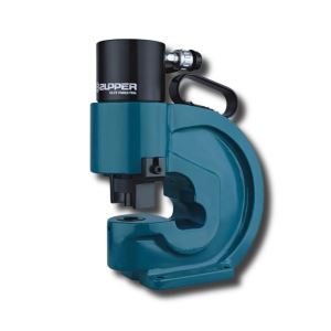
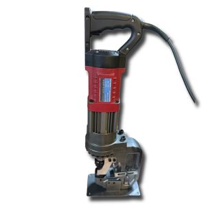
The Zupper manual hydraulic hole puncher CH-60 hydraulic hole puncher is specifically engineered to eliminate these fabrication anomalies. Designed as a heavy-duty C-frame hydraulic press, this equipment delivers a maximum rated load capacity of 30 tons (300 KN) to execute instantaneous punching operations. It is mechanically certified for punching through copper busbars, aluminum conductors, and mild carbon steel plates up to a strict maximum thickness of 6.0 mm. By transitioning from thermal-generating mechanical drilling to hydraulic punching, panel builders and structural steel fabricators ensure compliance with international electrical continuity standards while accelerating their workshop production cycles.

Zupper hydraulic hole puncher for 6mm metal CH-60
The fundamental engineering advantage of the hydraulic hole puncher CH-60 lies in its hydraulic punching mechanism. Unlike rotary cutting tools that aggressively shave the metal over an extended duration, the hydraulic punch utilizes instantaneous linear force to push a hardened steel punch through the 6mm target material and into a precision-matched receiving die.
This process preserves the metallurgical and electrical integrity of the busbar through several physical mechanisms:
Zero thermal degradation: The shearing action occurs in a fraction of a second, entirely bypassing the generation of a heat-affected zone. The copper or aluminum workpiece remains at ambient temperature throughout the fabrication cycle. This prevents localized annealing or hardening, which degrades electrical conductivity at the connection node.
Burr-free contact surfaces: The precise diametrical clearance between the CH-60’s upper punch and the lower receiving die creates a vertical, mirror-smooth shear plane. The resulting hole is completely devoid of raised burrs or sharp metallic edges. This guarantees surface-to-surface flush contact when high-tensile bolts are inserted and torqued, eliminating internal air gaps and minimizing electrical resistance.
Swarf elimination: Traditional drilling produces volumes of sharp metallic swarf that can contaminate sensitive electrical components within the workshop. The punching process generates only a single, solid metallic slug per operation, ensuring a clean fabrication environment that complies with stringent QA/QC facility standards.
Executing a 300KN continuous shear force imposes extreme kinetic stress on the structural housing of the equipment. If the housing lacks sufficient rigidity, the reactive forces cause the frame to temporarily flex (a phenomenon known as frame deflection). Structural deflection causes the upper punch to misalign with the lower die, resulting in asymmetric holes, accelerated tooling wear, or immediate die fracture.
To counteract these reactive forces, the Zupper CH-60 features a monolithic C-frame architecture forged from high-carbon cast steel.
Monolithic casting: Utilizing a continuous casting process rather than welding separate steel plates eliminates structural weak points and weld-seam fatigue. The uniform density of the cast steel provides an unyielding structure that absorbs and dissipates the 31-ton force linearly.
Optimized unit weight: The density of this cast steel frame results in a net weight of approximately 16.9 kg. While this classifies the CH-60 as a stationary workshop tool rather than a portable field device, this mass is an essential engineering parameter. The substantial unit weight anchors the tool securely to the workbench, dampening operational vibrations and maintaining absolute concentricity between the punch and die over thousands of industrial cycles.
In switchgear assembly, standard copper busbars frequently range from 40mm to 120mm in width. To align the connecting bolts properly and maintain safe dielectric clearances, the connection holes must be punched strictly along the longitudinal centerline of the busbar.
The CH-60 accommodates these dimensional requirements via its extended 90mm throat depth. This parameter defines the maximum distance from the center of the punching die to the inner back wall of the C-frame. A 90mm clearance ensures that technicians can position wide busbars deep into the jaw of the tool, allowing for center-punching on materials up to 180mm in total width. This spatial flexibility ensures that panel builders can adhere to the center-to-center hole distance specifications mandated by international electrical manufacturing standards.
To maximize tooling lifespan and ensure verifiable fabrication quality on 6mm metal, operators must implement the following systematic workflow:
Dimensional marking: Utilize a precision scribe or a digital layout gauge to mark the exact center-point of the required hole on the 6mm metal plate.
Die verification: Select the punch and die set that matches the specified bolt diameter. Critical safety mandate: Ensure the upper punch and the lower receiving die belong to the exact same dimensional set. Mixing unmatched tooling will result in catastrophic die failure under 30 tons of hydraulic pressure.
Tooling installation: Secure the receiving die into the lower base of the C-frame. Thread the corresponding punch into the upper hydraulic ram, ensuring the locking mechanisms are fully engaged.
Material positioning: Slide the 6mm workpiece into the 90mm throat. Align the scribed center-mark perfectly beneath the tip of the upper punch.
Hydraulic actuation: Activate the connected hydraulic pump. Once the punch makes contact with the material, the pressure will peak until the shear strength of the 6mm metal is overcome. An acoustic "pop" will indicate that the slug has been successfully sheared and ejected.
Retraction and slug clearance: Release the hydraulic pressure to retract the punch via the heavy-duty return spring. Visually confirm that the ejected metal slug has cleared the bottom exit chute before initiating the next cycle.
Sustaining the 31-ton maximum rated load capacity over an extended industrial lifecycle requires strict adherence to physical maintenance protocols:
Tooling inspection: Prior to every operational shift, inspect the cutting edges of the punch and the inner rim of the die for micro-chipping or dulling. Operating the tool with dull dies increases the required shearing force, putting unnecessary strain on the hydraulic cylinder and the C-frame.
Internal spring fatigue: The CH-60 relies on a heavy-duty internal spring to retract the punch after the shearing cycle. If the retraction process becomes sluggish, the spring may be experiencing mechanical fatigue and must be replaced to prevent the punch from jamming inside the 6mm workpiece.
Hydraulic seal integrity: Regularly inspect the quick-connect coupler and the main ram seal for hydraulic fluid seepage. A compromised seal will result in pressure loss, preventing the equipment from reaching its 300KN specification.
Incomplete shearing (Punch fails to penetrate 6mm material): This anomaly indicates a pressure drop in the hydraulic supply line. Verify that the external hydraulic pump is capable of reaching 700 bar (10,000 psi) and ensure the quick-connect couplers are securely fastened without air gaps.
Material distortion around the hole: If the 6mm metal plate bends or warps during the punching process, the diametrical clearance between the upper punch and the lower die is too large. Verify that you have not mismatched the punch and die sets.
Slug jamming in the exit chute: If successive metal slugs fail to drop through the lower die holder, halt operations immediately. Forcing another punch cycle on top of a jammed slug will cause irreversible structural damage to the C-frame. Manually clear the chute using a non-marring tool.
Engineers and procurement officers must verify compatibility with the following operational parameters prior to facility integration:
| Technical Parameter | Metric Value |
| Model | Zupper CH-60 |
| Tool classification | Single-acting hydraulic hole puncher |
| Maximum rated load capacity | 30 Ton (300 KN) |
| Throat depth (Clearance) | 90 mm |
| Max material thickness (All Metals) | 6.0 mm |
| Rated fluid pressure requirement | 700 bar (10,000 psi) |
| Net weight | 16.9 kg |
Standard tooling configuration:
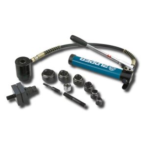
The CH-60 is delivered with a complete set of high-carbon, heat-treated steel dies designed for standard industrial metric bolts: 10.5mm, 13.8mm, 17mm, 20.5mm
The CH-60 is a dedicated hydraulic fabrication head without an internal fluid reservoir. To generate the required 300KN shearing force and penetrate 6mm metal safely, it must be paired with an external 700-bar (10,000 psi) hydraulic power unit. Based on your specific production environment, we suggest the following two operational configurations:
For continuous workshop production: Zupper TEP-700B Electric Hydraulic Pump We strictly mandate pairing the CH-60 with the TEP-700B for panel building facilities executing high-volume batch processing. This electric power unit delivers rapid, consistent fluid displacement to minimize punch cycle times. It features a remote foot-pedal actuator, which is a critical safety and precision requirement; it allows the operator to maintain two-handed mechanical control over the 6mm workpiece for exact center-mark alignment before initiating the 30-ton shear.

For localized field deployment: Zupper CP-700 Manual Hydraulic Pump For deployment in remote substations, offshore platforms, or maintenance environments lacking a stable electrical grid, the CH-60 must be operated via the CP-700 manual pump. Engineered with a dual-stage fluid displacement mechanism, this manual unit efficiently builds the required 700-bar pressure while maintaining a manageable net weight. It ensures field technicians can execute precise punching operations completely independent of external power sources. Click below picture for more information.

Asia Pro Equip supplies verified, heavy-duty fabrication solutions to the mechanical engineering, switchgear manufacturing, and civil construction sectors. We maintain strategic, ready-to-deploy inventory of the Zupper CH-60 puncher and its associated tooling configurations within our regional logistics hubs, ensuring efficient supply chain fulfillment to industrial zones across Singapore and Malaysia.
Operating on a strictly transparent B2B pricing model, our technical sales division is prepared to process your official RFQ, verify equipment compliances against your local engineering specifications, and fulfill your operational requirements.
Corporate Sales & RFQ: [email protected]
| Technical Parameter | Metric Value |
| Model | Zupper CH-60 |
| Tool classification | Single-acting hydraulic hole puncher |
| Maximum rated load capacity | 30 Ton (300 KN) |
| Throat depth (Clearance) | 90 mm |
| Max material thickness (All Metals) | 6.0 mm |
| Rated fluid pressure requirement | 700 bar (10,000 psi) |
| Net weight | 16.9 kg |
Standard tooling configuration:
The CH-60 is delivered with a complete set of high-carbon, heat-treated steel dies designed for standard industrial metric bolts: 10.5mm, 13.8mm, 17mm, 20.5mm
Find answers to common inquiries about our power tools and professional services
Address:
Phone: +65 8914 6529
Email: [email protected]

All prices are listed in USD and exclude local taxes (such as GST/SST).
Final billing may be converted to SGD or MYR based on prevailing exchange rates at the time of formal quotation.
asiaproequip.com - 2026